809 lines
27 KiB
Markdown
809 lines
27 KiB
Markdown
# 实战二|MQTT开发:如何实现联网控制?
|
||
|
||
你好,我是郭朝斌。
|
||
|
||
在上一节中,我们基于平头哥RVB2601开发板完成了智能电灯硬件的搭建和嵌入式应用的开发,但是打造一款物联网设备,我们还需要将硬件接入物联网平台。接下来,我就来讲解一下RVB2601开发板通过MQTT协议接入阿里云生活物联网平台的流程及方法。
|
||
|
||
在开始本节内容的阅读之前,你可以重新打开[第17讲](https://time.geekbang.org/column/article/322528),了解一下Python语言的实现代码。对比着本节的C语言代码,你将会对程序开发有更深入的理解。
|
||
|
||
## 生活物联网平台的准备工作
|
||
|
||
阿里云生活物联网平台,又称为飞燕平台,是面向消费级产品的物联网开放平台。它具备完整的、面向家居物联网场景的功能定义,可以非常方便地完成智能设备的物联网接入工作。
|
||
|
||
接下来,我们就在这个平台上完成智能灯的联网控制实验。
|
||
|
||
### 创建项目和产品
|
||
|
||
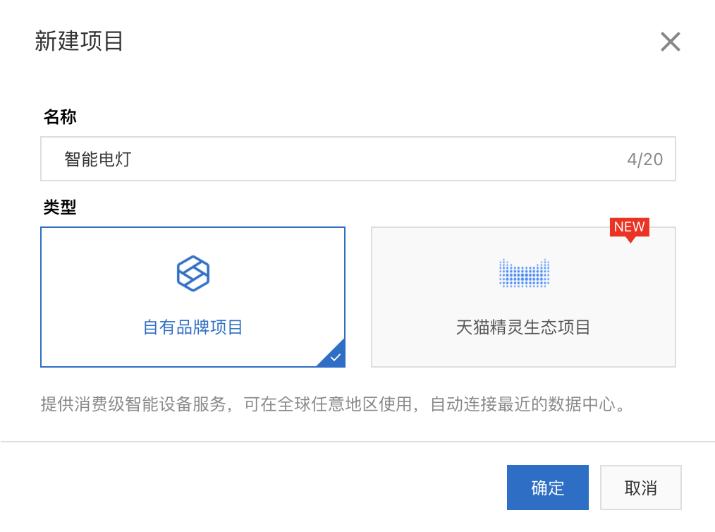
首先,登录[生活物联网平台](https://living.aliyun.com),我们进行第一个项目的创建。项目的名称,我们可以填写“智能电灯”。对于项目类型,你可以根据产品需求来决定,因为我们不计划接入天猫精灵生态,所以这里选择“自有品牌项目”。
|
||
|
||
|
||
|
||
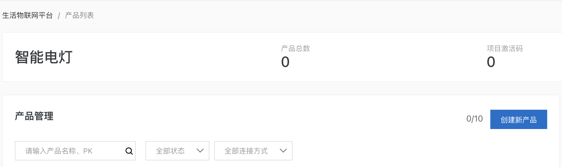
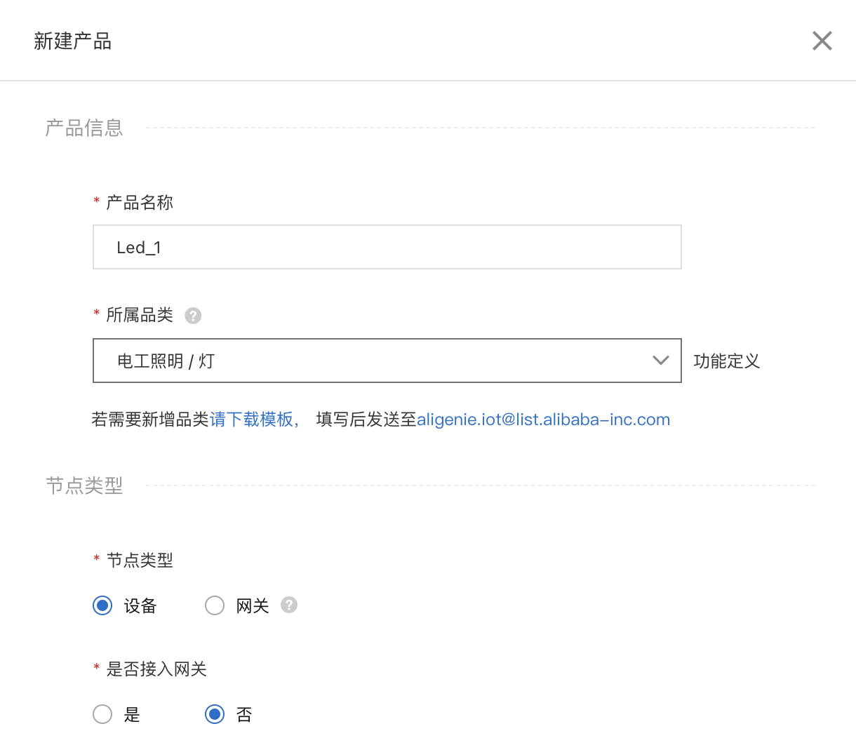
接着,我们为这个“智能电灯”项目创建一个新产品“Led\_1”。
|
||
|
||
|
||
|
||
产品的参数可以这样设置:
|
||
|
||
* 所属品类,选择“电工照明”–>“灯”。
|
||
* 节点设备,选择“设备”。是否接入网关,选择“否”。
|
||
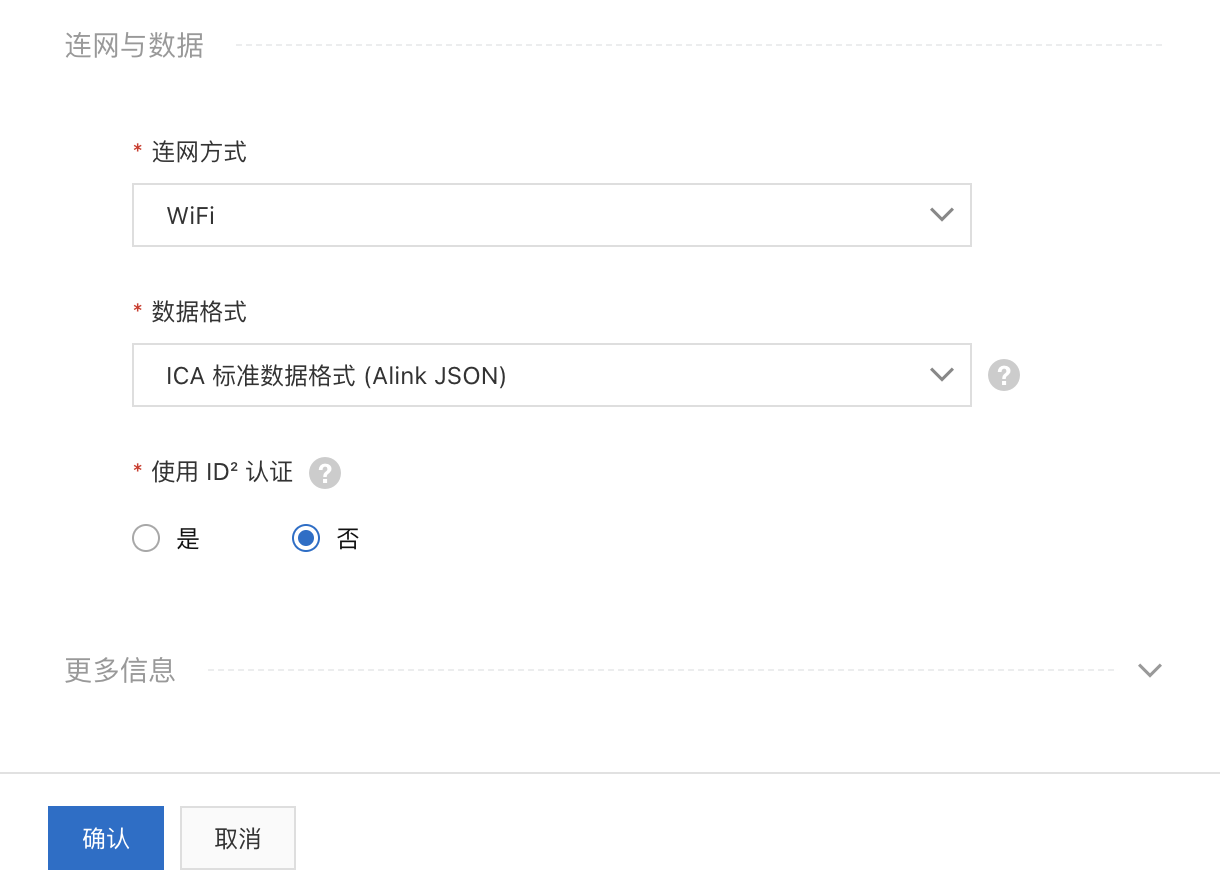
* 连网方式,选择“WiFi”。
|
||
* 数据格式,选择“ICA标准数据格式(Alink JSON)”。
|
||
|
||
|
||
|
||
|
||
### 产品功能定义
|
||
|
||
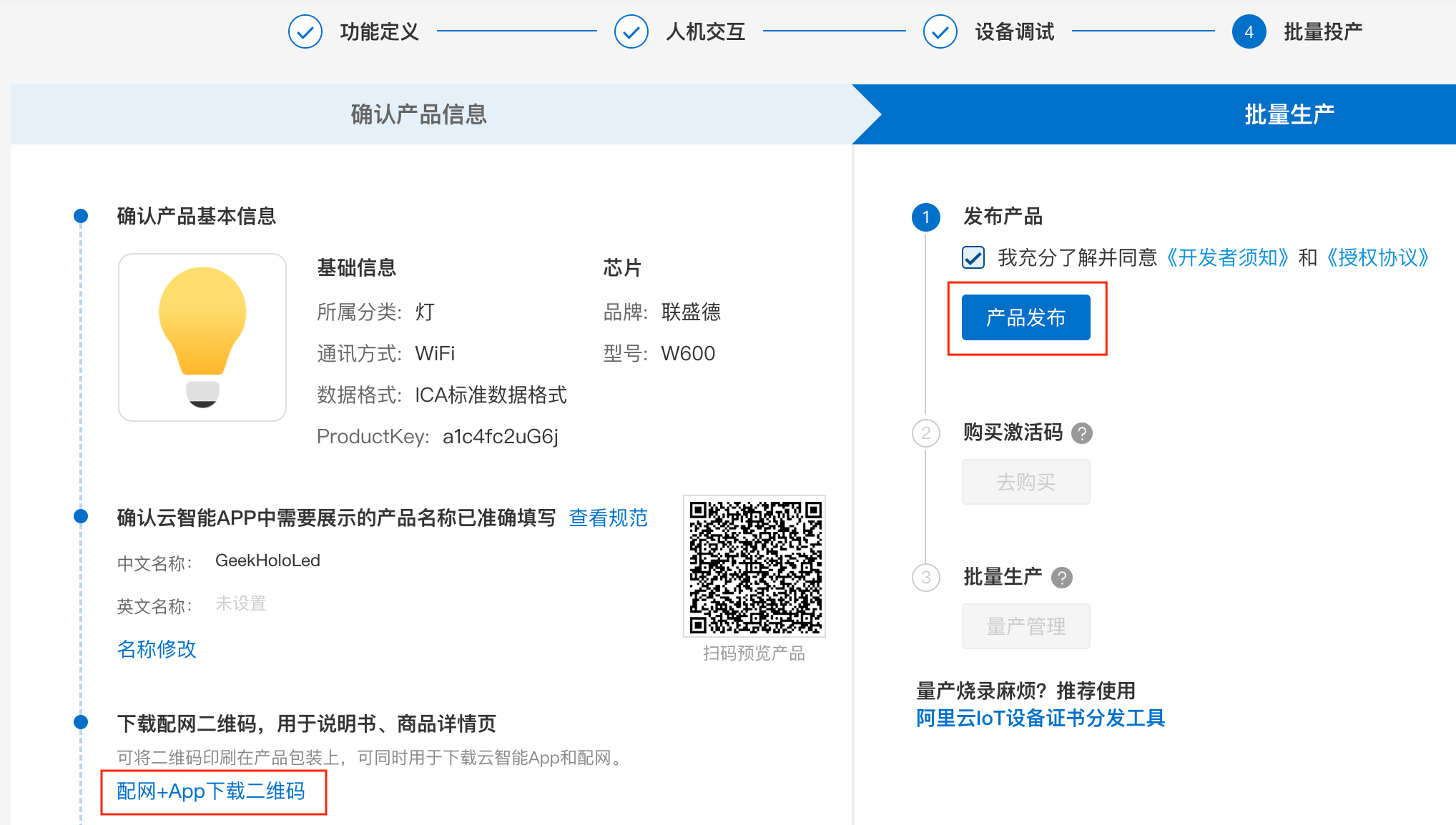
创建完产品,我们进入产品的研发流程。物联网平台把流程分为4个阶段,分别是:功能定义、人机交互、设备调试和批量投产。
|
||
|
||
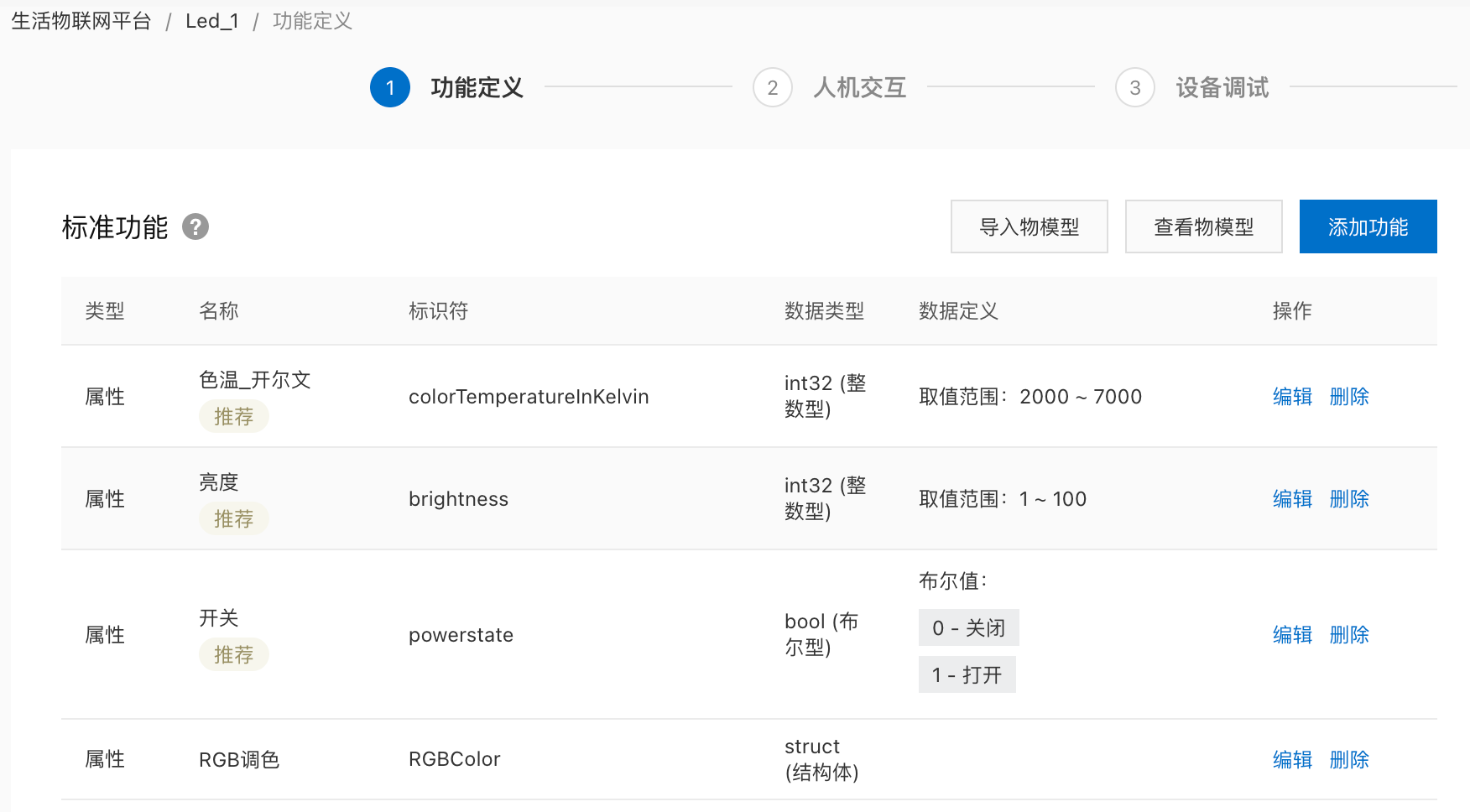
首先,我们来完成功能定义的部分,也就是物联网设备的物模型定义。
|
||
|
||
基于创建产品时我们选择的产品类型和数据格式,平台已经为智能电灯自动生成了一个标准的物模型。针对你开发的智能灯的功能需求,你可以对各项功能进行编辑、删除,或者新增标准模版没有的功能。比如像我这里展示的一样,保留“开关”、“亮度”和“色温”,删除其他功能项,同时增加“RGB调色”功能。“RGB调色”功能项,对应了我们智能灯的三色LED模块。
|
||
|
||
|
||
|
||
### 人机交互设计
|
||
|
||
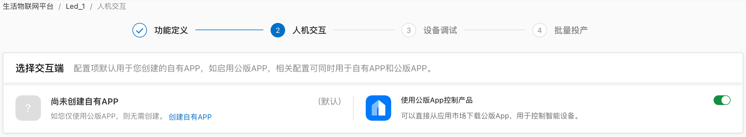
完成功能定义后,我们进入下一步,人机交互。在人机交互中,我们主要完成配网方式和手机App相关界面的设计。
|
||
|
||
首先,我们选择使用公版App控制产品。这样可以省掉我们开发独立App的工作。
|
||
|
||
|
||
|
||
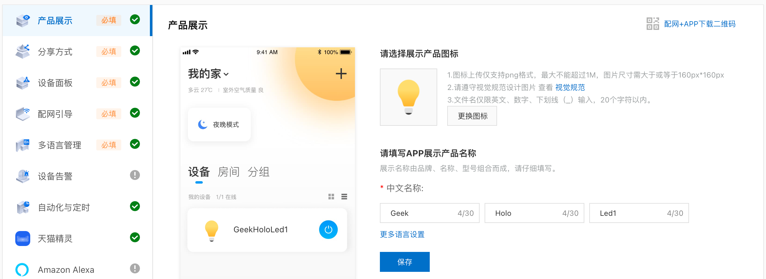
在“产品展示”标签页中,设置一下产品名称。
|
||
|
||
|
||
|
||
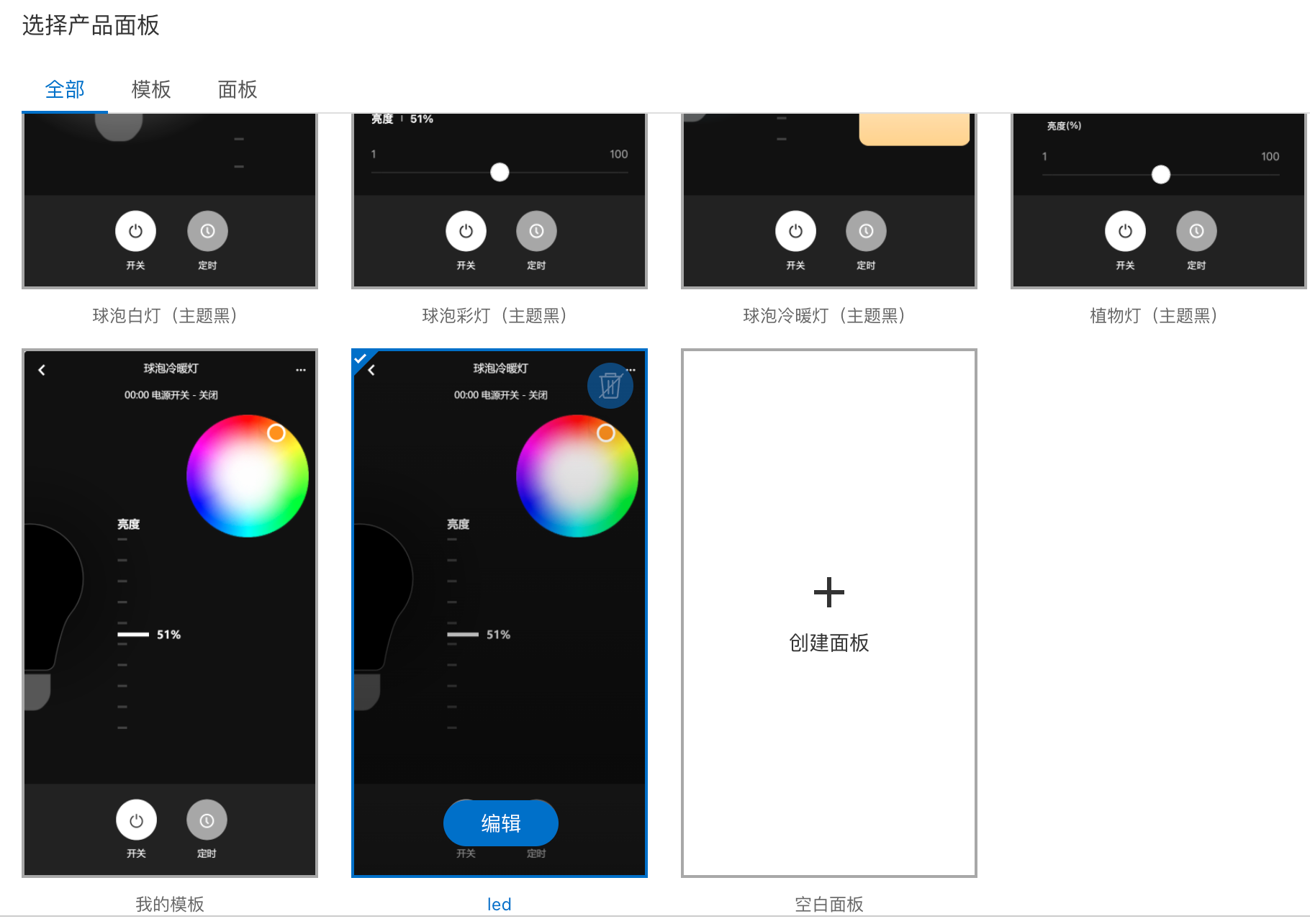
在“设备面板”中,你可以点击进入“选择面板”页面,选择一个智能灯在App上的展示和操作界面。因为默认面板中没有适配“RGB调色”的面板,所以,你需要编辑一下“灯泡冷暖灯”模版来替代使用。否则,平台会显示错误信息,提示面板与物模型的属性定义不一致。
|
||
|
||
|
||
|
||
配网方式,我们保持默认设置即可。在“自动化与定时”标签页中,我们要勾选“开关”的“作为执行”选项。这样,在自动化场景的创建中,智能电灯的开关就可以作为执行动作起到控制的效果了。
|
||
|
||
### 设备调试设置
|
||
|
||
在设备调试页面中,我们需要先选择产品使用的芯片或者模组。对于我们的实验项目,这里直接选择列表最后一项——未知芯片即可。
|
||
|
||
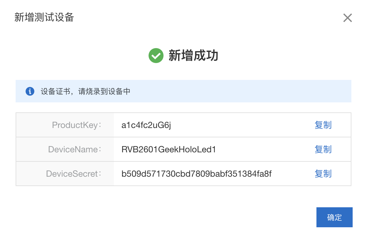
然后,我们新建一个测试设备。因为我们需要获得一个设备证书,也就是智能灯连接物联网平台的五元组信息。
|
||
|
||
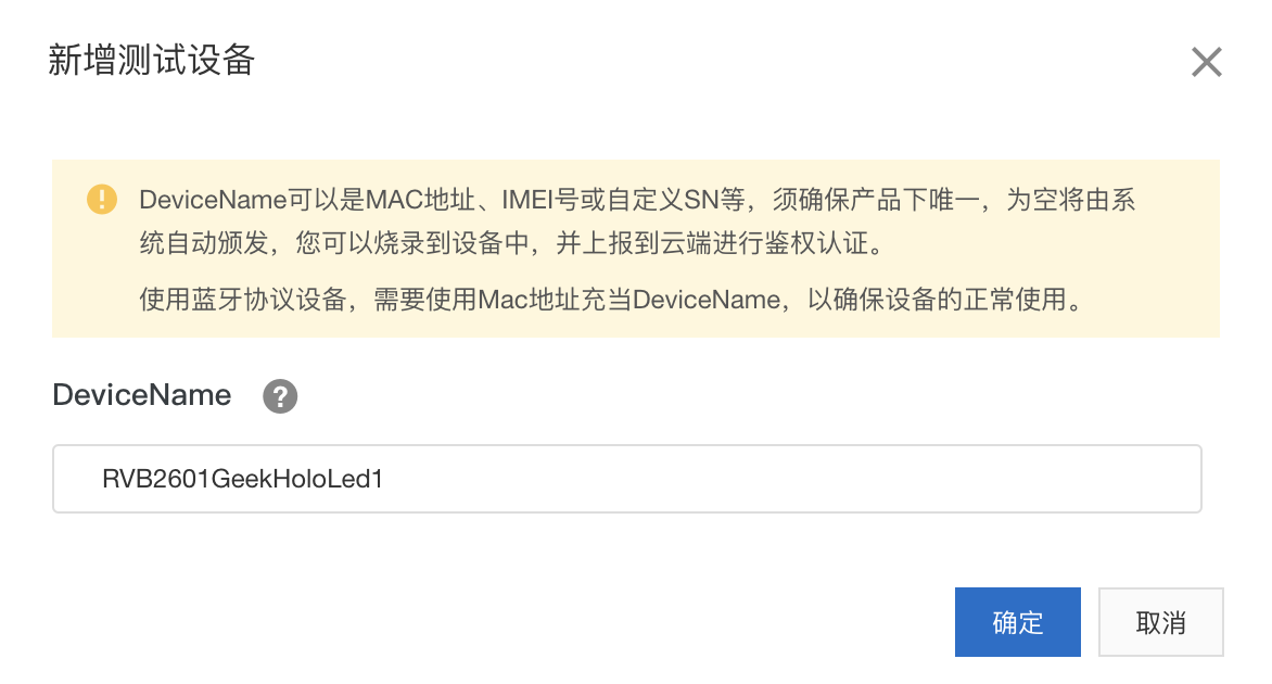
点击“新建测试设备”,你需要为测试设备输入一个名称,比如,可以是“RVB2601HoloLed1”。然后,点击“确定”,页面就会新增一个设备条目。
|
||
|
||
|
||
|
||
在新增设备条目中,点击“设备证书”,你就可以看到设备五元组信息。这里要记得复制、保存这些字符串,因为我们在后面的应用代码中需要用到。
|
||
|
||
|
||
|
||
你可以看到,这个新增测试设备的状态显示“未激活”。因为只有当设备通过MQTT协议第一次连接到物联网平台后,这个测试设备才会被激活,并且可以发送消息进行在线调试。
|
||
|
||
## 智能灯如何接入物联网
|
||
|
||
那么,智能灯如何接入物联网平台实现后续的调试、使用呢?下面,我们来开发一下智能灯的联网控制功能。
|
||
|
||
### 联网功能开发
|
||
|
||
RVB2601开发板中的W800模组提供了Wi-Fi和BLE通信能力,而且模组还集成了连接阿里云生活物联网平台(飞燕)的功能。主控芯片CH2601通过SPI接口与W800模组通信,它只需要发送/接收W800定义的AT指令,就可以实现相应的功能。
|
||
|
||
W800模组的AT指令集可以参考[官方文档](https://occ-oss-prod.oss-cn-hangzhou.aliyuncs.com/userFiles/3717897501090217984/resource/3717897501090217984XBSRZBtccb.pdf)。我们就基于文档中飞燕平台的相关AT指令来实现与平台的通信。它的底层实现依然是MQTT协议,不过封装成了AT指令的接口形式。
|
||
|
||
这里,我们就需要修改W800的驱动代码,增加联网接口函数,其中具体包括:
|
||
|
||
* 设置设备五元组接口
|
||
* 建立MQTT连接接口
|
||
* 物模型属性设置回调注册接口
|
||
* 物模型属性上报接口
|
||
|
||
具体要怎么做呢?
|
||
|
||
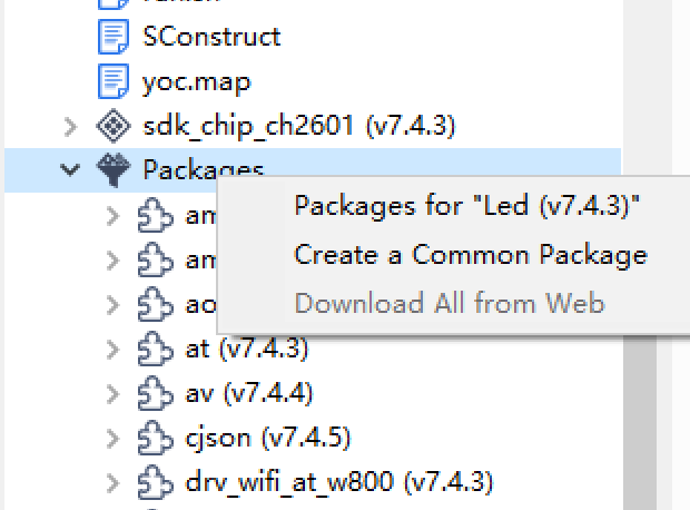
我们需要在项目中引入W800的驱动模块drv\_wifi\_at\_w800。在CDK中,点击右键打开“Packages for Led”,在模块窗口左侧找到drv\_wifi\_at\_w800模块,点击箭头导入右侧列表中。
|
||
|
||
|
||

|
||
|
||
在W800的驱动模块drv\_wifi\_at\_w800中,打开w800\_api.h文件,增加函数接口定义。
|
||
|
||
```c++
|
||
int w800_living_idmau(const char *mykey,const char *myname,const char *mysecret,const char *mypsecret);
|
||
int w800_living_idmcon(void);
|
||
void w800_living_recv_callback_register(const char *cmd, void *callback, void *context);
|
||
int w800_living_send_attribute(const char *dev_id, const char *msg);
|
||
|
||
```
|
||
|
||
在w800\_api.c文件中,增加函数接口的实现代码。
|
||
|
||
```c++
|
||
int w800_living_idmau(const char *mykey,const char *myname,const char *mysecret,const char *mypsecret)
|
||
{
|
||
int ret = -1;
|
||
|
||
aos_mutex_lock(&g_cmd_mutex,AOS_WAIT_FOREVER);
|
||
|
||
atparser_clr_buf(g_atparser_uservice_t);
|
||
|
||
if (atparser_send(g_atparser_uservice_t,
|
||
"AT+IDMAU=\"%s\",\"%s\",\"%s\",\"%s\"", mykey, myname, mysecret, mypsecret) == 0) {
|
||
if (atparser_recv(g_atparser_uservice_t, "OK\n") == 0) {
|
||
ret = 0;
|
||
}
|
||
else {
|
||
printf("Destination Host Unreachable!\r\n");
|
||
}
|
||
}
|
||
|
||
atparser_cmd_exit(g_atparser_uservice_t);
|
||
|
||
if (ret == 0) {
|
||
printf("key = %s name = %s secret = %s psecret = %s!\r\n", mykey, myname, mysecret, mypsecret);
|
||
}
|
||
|
||
aos_mutex_unlock(&g_cmd_mutex);
|
||
return ret;
|
||
}
|
||
|
||
int w800_living_idmcon(void)
|
||
{
|
||
int ret = -1;
|
||
|
||
aos_mutex_lock(&g_cmd_mutex,AOS_WAIT_FOREVER);
|
||
|
||
atparser_clr_buf(g_atparser_uservice_t);
|
||
|
||
if (atparser_send(g_atparser_uservice_t, "AT+IDMCON") == 0) {
|
||
if (atparser_recv(g_atparser_uservice_t, "OK\n") == 0) {
|
||
ret = 0;
|
||
} else {
|
||
printf("Destination Host Unreachable!\r\n");
|
||
}
|
||
}
|
||
|
||
atparser_cmd_exit(g_atparser_uservice_t);
|
||
|
||
if (ret == 0) {
|
||
printf("AT+IDMCON \r\n");
|
||
}
|
||
|
||
aos_mutex_unlock(&g_cmd_mutex);
|
||
return ret;
|
||
}
|
||
|
||
void w800_living_recv_callback_register(const char *cmd, void *callback, void *context)
|
||
{
|
||
atparser_oob_create(g_atparser_uservice_t, cmd, callback, context);
|
||
}
|
||
|
||
int w800_living_send_attribute(const char *dev_id, const char *msg)
|
||
{
|
||
int ret = -1;
|
||
|
||
if (!dev_id || !msg) {
|
||
return ret;
|
||
}
|
||
|
||
aos_mutex_lock(&g_cmd_mutex, AOS_WAIT_FOREVER);
|
||
|
||
atparser_clr_buf(g_atparser_uservice_t);
|
||
|
||
printf("Send msg: %s\r\n", msg);
|
||
if (atparser_send(g_atparser_uservice_t, "AT+IDMPP=0,\"%s\"", msg) == 0) {
|
||
if (atparser_recv(g_atparser_uservice_t, "OK\n") == 0) {
|
||
ret = 0;
|
||
printf("Send at cmd ok\n");
|
||
}
|
||
} else {
|
||
printf("Send at cmd err\n");
|
||
}
|
||
|
||
atparser_cmd_exit(g_atparser_uservice_t);
|
||
|
||
aos_mutex_unlock(&g_cmd_mutex);
|
||
|
||
return ret;
|
||
}
|
||
|
||
```
|
||
|
||
这里,物模型属性设置回调注册接口的实现采用了非侵入的方式,以尽量减少对原代码的修改。所以,这就需要接口调用者,在应用代码中明确地指定AT指令的代码。通常来说,更好的实现方式是通过消息机制来实现,但是这需要定义唯一的、不冲突的消息编号,并且在w800\_module\_init函数体中增加回调注册代码,侵入性太大,所以并没有选择这样的实现方式。
|
||
|
||
### 智能灯平台交互的封装
|
||
|
||
对于智能灯与平台之间的交互逻辑,我们可以新建代码来封装实现。在C语言中,为方便接口函数的调用,我们需要先新建一个头文件—— app\_living.h 。
|
||
|
||
```c++
|
||
#ifndef __APP_LIVING_H__
|
||
#define __APP_LIVING_H__
|
||
|
||
#include <uservice/eventid.h>
|
||
|
||
#ifdef __cplusplus
|
||
extern "C" {
|
||
#endif
|
||
|
||
#define EVENT_LIVING_ATTR_POWER (EVENT_USER + 1)
|
||
#define EVENT_LIVING_ATTR_BRIGHTNESS (EVENT_USER + 2)
|
||
#define EVENT_LIVING_ATTR_COLOR (EVENT_USER + 3)
|
||
|
||
typedef struct RgbColor
|
||
{
|
||
unsigned char r;
|
||
unsigned char g;
|
||
unsigned char b;
|
||
} RgbColor;
|
||
|
||
void update_attr(uint8_t powerstate, uint8_t bright, RgbColor rgb);
|
||
|
||
int connect_iot_demo(void);
|
||
|
||
#ifdef __cplusplus
|
||
}
|
||
#endif
|
||
|
||
#endif /* __APP_LIVING_H__ */
|
||
|
||
```
|
||
|
||
然后,新建app\_living.c源文件来实现代码逻辑。为了解析从平台发送的JSON格式消息,我们引入了cJSON模块。
|
||
|
||
```c++
|
||
#include <stdlib.h>
|
||
#include <string.h>
|
||
#include <aos/debug.h>
|
||
#include <devices/w800.h>
|
||
#include <yoc/atparser.h>
|
||
#include "cJSON.h"
|
||
#include "app_living.h"
|
||
|
||
#define TAG "app_living"
|
||
|
||
extern int w800_living_idmau(const char *mykey,const char *myname,const char *mysecret,const char *mypsecretconst);
|
||
extern int w800_living_idmcon(void);
|
||
extern void w800_living_recv_callback_register(const char *cmd, void *callback, void *context);
|
||
extern int w800_living_send_attribute(const char *dev_id, const char *msg);
|
||
|
||
void update_attr(uint8_t powerstate, uint8_t bright, RgbColor rgb)
|
||
{
|
||
printf("enter update \n");
|
||
const char *dev_id = "0";
|
||
char msg[128] = {0};
|
||
const char *msg_format = "{\\\"powerstate\\\":%d,\\\"brightness\\\":%d,\\\"RGBColor\\\":{\\\"Red\\\":%d,\\\"Green\\\":%d,\\\"Blue\\\":%d}}";
|
||
|
||
sprintf(msg, msg_format, powerstate, bright, rgb.r,rgb.g,rgb.b);
|
||
|
||
w800_living_send_attribute(dev_id, msg);
|
||
}
|
||
|
||
static int parse_living_msg(const char *msg)
|
||
{
|
||
cJSON *root = NULL;
|
||
|
||
/* Parse Root */
|
||
root = cJSON_Parse(msg);
|
||
if (root == NULL || !cJSON_IsObject(root)) {
|
||
printf("JSON Parse Error\n");
|
||
return -1;
|
||
}
|
||
cJSON *item = cJSON_GetObjectItem(root, "powerstate");
|
||
static uint8_t power_on;
|
||
if (item && cJSON_IsNumber(item)) {
|
||
if (item->valueint) {
|
||
power_on = 1;
|
||
} else {
|
||
power_on = 0;
|
||
}
|
||
event_publish(EVENT_LIVING_ATTR_POWER, &power_on);
|
||
}
|
||
|
||
item = cJSON_GetObjectItem(root, "brightness");
|
||
static uint8_t bright;
|
||
if (item && cJSON_IsNumber(item)) {
|
||
bright = item->valueint;
|
||
event_publish(EVENT_LIVING_ATTR_BRIGHTNESS, &bright);
|
||
}
|
||
|
||
item = cJSON_GetObjectItem(root, "RGBColor");
|
||
static RgbColor rgb;
|
||
if (item && cJSON_IsObject(item)) {
|
||
cJSON *sub_item = cJSON_GetObjectItem(item, "Red");
|
||
if (sub_item && cJSON_IsNumber(sub_item)) {
|
||
rgb.r = sub_item->valueint;
|
||
}
|
||
sub_item = cJSON_GetObjectItem(item, "Green");
|
||
if (sub_item && cJSON_IsNumber(sub_item)) {
|
||
rgb.g = sub_item->valueint;
|
||
}
|
||
sub_item = cJSON_GetObjectItem(item, "Blue");
|
||
if (sub_item && cJSON_IsNumber(sub_item)) {
|
||
rgb.b = sub_item->valueint;
|
||
}
|
||
event_publish(EVENT_LIVING_ATTR_COLOR, &rgb);
|
||
}
|
||
|
||
cJSON_Delete(root);
|
||
|
||
return 0;
|
||
}
|
||
|
||
static int living_set_attr_callback(atparser_uservice_t *at, void *priv, oob_data_t *oob_data)
|
||
{
|
||
int did = 0;
|
||
int len = 0;
|
||
char msg[128] = {0};
|
||
char *str = strchr(oob_data->buf, ':');
|
||
if (str != NULL) {
|
||
sscanf(oob_data->buf, "%d,%d,%s\r\n", &did, &len, msg);
|
||
LOGD(TAG,"==>recv data %d(%d):%s\r\n",did, len, msg);
|
||
parse_living_msg(msg);
|
||
oob_data->used_len = len;
|
||
}
|
||
|
||
return 0;
|
||
}
|
||
|
||
int connect_iot_demo(void)
|
||
{
|
||
char *my_key = "a1AMULi68xV";//ProductKey
|
||
char *my_name = "RVB2601GeekHoloLed1";//DeviceName
|
||
char *my_secret = "fcdf55e206b907d649e2249aed8c948a";//DeviceSecret
|
||
char *my_p_secret = "BReZtzPVrLcdY1H4";//Product Secret
|
||
|
||
int ret2 = -1;
|
||
int ret3 = -1;
|
||
|
||
w800_living_recv_callback_register("+IDMPS:", living_set_attr_callback, NULL);
|
||
|
||
ret2 = w800_living_idmau(my_key,my_name,my_secret,my_p_secret);
|
||
|
||
if (ret2 == 0){
|
||
printf("AT+IDMAU:OK!\n");
|
||
} else {
|
||
printf("AT+IDMAU:ERROR!\n");
|
||
}
|
||
|
||
ret3 = w800_living_idmcon();
|
||
if (ret3 == 0){
|
||
printf("AT+IDMCON:OK!\n");
|
||
} else {
|
||
printf("AT+IDMCON:ERROR!\n");
|
||
}
|
||
|
||
if(ret2 == 0 && ret3 == 0){
|
||
return 0;
|
||
}else{
|
||
return -1;
|
||
}
|
||
}
|
||
|
||
```
|
||
|
||
> 注意替换上面代码中connect\_iot\_demo函数使用的设备五元组信息。
|
||
|
||
### LED颜色控制实现
|
||
|
||
为了控制亮度,我们也需要对上一节中的LED控制代码进行改造,具体代码如下。
|
||
|
||
```c++
|
||
|
||
/*********************
|
||
* INCLUDES
|
||
*********************/
|
||
#define _DEFAULT_SOURCE /* needed for usleep() */
|
||
#include <stdio.h>
|
||
#include <stdlib.h>
|
||
#include <unistd.h>
|
||
#include <time.h>
|
||
#include <aos/aos.h>
|
||
#include "app_config.h"
|
||
#include "app_main.h"
|
||
#include "csi_config.h"
|
||
|
||
#include "board_config.h"
|
||
#include "drv/gpio_pin.h"
|
||
#include <drv/pin.h>
|
||
#include <drv/pwm.h>
|
||
|
||
#ifdef CONFIG_PWM_MODE
|
||
|
||
static csi_pwm_t r;
|
||
|
||
void led_pinmux_init()
|
||
{
|
||
//7
|
||
csi_error_t ret;
|
||
csi_pin_set_mux(PA7, PA7_PWM_CH7);
|
||
csi_pin_set_mux(PA25, PA25_PWM_CH2);
|
||
csi_pin_set_mux(PA4, PA4_PWM_CH4);
|
||
|
||
ret = csi_pwm_init(&r, 0);
|
||
if (ret != CSI_OK) {
|
||
printf("===%s, %d\n", __FUNCTION__, __LINE__);
|
||
return ;
|
||
}
|
||
}
|
||
|
||
void rgb_light(uint32_t red, uint32_t green, uint32_t blue, uint8_t brightness)
|
||
{
|
||
csi_error_t ret;
|
||
ret = csi_pwm_out_config(&r, 7 / 2, 300, red*300*brightness/100/255, PWM_POLARITY_HIGH);
|
||
if (ret != CSI_OK) {
|
||
printf("===%s, %d\n", __FUNCTION__, __LINE__);
|
||
return ;
|
||
}
|
||
ret = csi_pwm_out_start(&r, 7 / 2);
|
||
if (ret != CSI_OK) {
|
||
printf("===%s, %d\n", __FUNCTION__, __LINE__);
|
||
return ;
|
||
}
|
||
//25
|
||
ret = csi_pwm_out_config(&r, 2 / 2, 300, green*300*brightness/100/255, PWM_POLARITY_HIGH);
|
||
if (ret != CSI_OK) {
|
||
printf("===%s, %d\n", __FUNCTION__, __LINE__);
|
||
return ;
|
||
}
|
||
ret = csi_pwm_out_start(&r, 2 / 2);
|
||
if (ret != CSI_OK) {
|
||
printf("===%s, %d\n", __FUNCTION__, __LINE__);
|
||
return ;
|
||
}
|
||
//4
|
||
ret = csi_pwm_out_config(&r, 4 / 2, 300, blue*300*brightness/100/255, PWM_POLARITY_HIGH);
|
||
if (ret != CSI_OK) {
|
||
printf("===%s, %d\n", __FUNCTION__, __LINE__);
|
||
return ;
|
||
}
|
||
ret = csi_pwm_out_start(&r, 4 / 2);
|
||
if (ret != CSI_OK) {
|
||
printf("===%s, %d\n", __FUNCTION__, __LINE__);
|
||
return ;
|
||
}
|
||
}
|
||
#endif
|
||
|
||
#ifdef CONFIG_GPIO_MODE
|
||
static uint32_t g_ctr = 0;
|
||
static csi_gpio_pin_t r;
|
||
static csi_gpio_pin_t g;
|
||
static csi_gpio_pin_t b;
|
||
void led_pinmux_init()
|
||
{
|
||
csi_pin_set_mux(PA7, PIN_FUNC_GPIO);
|
||
csi_pin_set_mux(PA25, PIN_FUNC_GPIO);
|
||
csi_pin_set_mux(PA4, PIN_FUNC_GPIO);
|
||
csi_gpio_pin_init(&r, PA7);
|
||
csi_gpio_pin_dir(&r, GPIO_DIRECTION_OUTPUT);
|
||
csi_gpio_pin_mode(&r, GPIO_MODE_PUSH_PULL);
|
||
csi_gpio_pin_init(&g, PA25);
|
||
csi_gpio_pin_dir(&g, GPIO_DIRECTION_OUTPUT);
|
||
csi_gpio_pin_mode(&g, GPIO_MODE_PUSH_PULL);
|
||
csi_gpio_pin_init(&b, PA4);
|
||
csi_gpio_pin_dir(&b, GPIO_DIRECTION_OUTPUT);
|
||
csi_gpio_pin_mode(&b, GPIO_MODE_PUSH_PULL);
|
||
g_ctr = 0;
|
||
}
|
||
|
||
//fake rgb, because of only high or low state of gpio
|
||
void rgb_light(uint32_t red, uint32_t green, uint32_t blue)
|
||
{
|
||
(red < 50)?csi_gpio_pin_write(&r, GPIO_PIN_LOW):csi_gpio_pin_write(&r, GPIO_PIN_HIGH);
|
||
(green < 50)?csi_gpio_pin_write(&r, GPIO_PIN_LOW):csi_gpio_pin_write(&g, GPIO_PIN_HIGH);
|
||
(blue < 50)?csi_gpio_pin_write(&r, GPIO_PIN_LOW):csi_gpio_pin_write(&b, GPIO_PIN_HIGH);
|
||
}
|
||
#endif
|
||
|
||
|
||
```
|
||
|
||
### 继电器状态获取实现
|
||
|
||
为了获取继电器状态,也就是LED灯的开关状态,我们同样需要对继电器代码进行改造。具体代码如下。
|
||
|
||
```c++
|
||
/*********************
|
||
* INCLUDES
|
||
*********************/
|
||
#define _DEFAULT_SOURCE /* needed for usleep() */
|
||
#include <stdio.h>
|
||
#include <stdlib.h>
|
||
#include <unistd.h>
|
||
#include <time.h>
|
||
#include <aos/aos.h>
|
||
#include "app_config.h"
|
||
#include "csi_config.h"
|
||
#include "app_main.h"
|
||
|
||
#include "board_config.h"
|
||
#include "drv/gpio_pin.h"
|
||
#include <drv/pin.h>
|
||
|
||
static csi_gpio_pin_t relay;
|
||
|
||
unsigned char get_state()
|
||
{
|
||
return csi_gpio_pin_read(&relay);
|
||
}
|
||
|
||
void relay_pinmux_init()
|
||
{
|
||
csi_pin_set_mux(PA26, PIN_FUNC_GPIO);
|
||
csi_gpio_pin_init(&relay, PA26);
|
||
csi_gpio_pin_dir(&relay, GPIO_DIRECTION_OUTPUT);
|
||
}
|
||
|
||
void relay_toggle(bool on)
|
||
{
|
||
if(on)
|
||
{
|
||
csi_gpio_pin_write(&relay, GPIO_PIN_HIGH);
|
||
}
|
||
else
|
||
{
|
||
csi_gpio_pin_write(&relay, GPIO_PIN_LOW);
|
||
}
|
||
}
|
||
|
||
|
||
```
|
||
|
||
### 网络初始化实现
|
||
|
||
在编写应用的主逻辑之前,我们需要先对RVB2601开发板进行初始化。其中,网络初始化是我们为实现联网新增的代码逻辑。
|
||
|
||
网络初始化分为两步。第一步是初始化W800模块:在设置好GPIO口、波特率和缓冲大小后,通过调用wifi\_w800\_register函数初始化;第二步是配置网络管理器(netmgr)模块:这里你需要将netmgr\_config\_wifi函数中的入参替换成自己的Wi-Fi网络SSID和密码,并且注意修改入参中的数字为SSID字符串和密码字符串的长度。
|
||
|
||
```c++
|
||
#include <stdbool.h>
|
||
#include <aos/kv.h>
|
||
#include <yoc/partition.h>
|
||
#include <yoc/init.h>
|
||
#include <drv/pin.h>
|
||
#include <yoc/at_port.h>
|
||
#include <devices/w800.h>
|
||
#include <devices/drv_snd_alkaid.h>
|
||
|
||
#include "app_main.h"
|
||
#include "board.h"
|
||
|
||
#define TAG "init"
|
||
|
||
netmgr_hdl_t app_netmgr_hdl;
|
||
extern at_channel_t spi_channel;
|
||
|
||
static void network_init()
|
||
{
|
||
w800_wifi_param_t w800_param;
|
||
/* init wifi driver and network */
|
||
w800_param.reset_pin = PA21;
|
||
w800_param.baud = 1*1000000;
|
||
w800_param.cs_pin = PA15;
|
||
w800_param.wakeup_pin = PA25;
|
||
w800_param.int_pin = PA22;
|
||
w800_param.channel_id = 0;
|
||
w800_param.buffer_size = 4*1024;
|
||
|
||
wifi_w800_register(NULL, &w800_param);
|
||
app_netmgr_hdl = netmgr_dev_wifi_init();
|
||
|
||
if (app_netmgr_hdl) {
|
||
utask_t *task = utask_new("netmgr", 2 * 1024, QUEUE_MSG_COUNT, AOS_DEFAULT_APP_PRI);
|
||
netmgr_service_init(task);
|
||
netmgr_config_wifi(app_netmgr_hdl, "你的wifi SSID", 11, "你的wifi AP密码", 11);
|
||
netmgr_start(app_netmgr_hdl);
|
||
}
|
||
}
|
||
|
||
void board_yoc_init(void)
|
||
{
|
||
board_init();
|
||
event_service_init(NULL);
|
||
console_init(CONSOLE_UART_IDX, 115200, 512);
|
||
ulog_init();
|
||
aos_set_log_level(AOS_LL_DEBUG);
|
||
|
||
int ret = partition_init();
|
||
if (ret <= 0) {
|
||
LOGE(TAG, "partition init failed");
|
||
} else {
|
||
LOGI(TAG, "find %d partitions", ret);
|
||
}
|
||
|
||
aos_kv_init("kv");
|
||
|
||
network_init();
|
||
|
||
board_cli_init();
|
||
}
|
||
|
||
|
||
```
|
||
|
||
### 智能灯主逻辑实现
|
||
|
||
在完成了W800驱动程序的增补、平台交互功能的封装以及LED模块、继电器代码的改造等一系列准备之后,我们就可以编写智能灯的主逻辑了。智能灯的主逻辑在app\_main.c文件中实现。
|
||
|
||
主逻辑包含几个模块:首先是初始化开发板、LED灯和继电器模块;然后是注册网络管理器事件的回调函数,和注册我们在平台交互模块中定义的属性设置事件的回调函数;最后,就是在while循环中建立物联网平台连接,并定期上报智能灯状态。
|
||
|
||
我们看一下具体的代码:
|
||
|
||
```c++
|
||
#include <stdlib.h>
|
||
#include <string.h>
|
||
#include <aos/list.h>
|
||
#include <aos/debug.h>
|
||
#include <uservice/uservice.h>
|
||
#include <uservice/eventid.h>
|
||
#include <yoc/sysinfo.h>
|
||
#include <board.h>
|
||
#include "drv/gpio_pin.h"
|
||
#include <drv/pin.h>
|
||
#include <drv/pwm.h>
|
||
#include "app_living.h"
|
||
#include "app_main.h"
|
||
|
||
#define TAG "APP"
|
||
|
||
static bool g_wifi_ok;
|
||
static uint8_t led_brightness;
|
||
static RgbColor led_color;
|
||
|
||
static void led_control(uint8_t power) {
|
||
relay_toggle(power);
|
||
}
|
||
|
||
static void led_set_brightness(uint8_t bright) {
|
||
led_brightness = bright;
|
||
rgb_light(led_color.r, led_color.g, led_color.b, bright);
|
||
}
|
||
|
||
static void led_set_color(RgbColor color) {
|
||
led_color.r = color.r;
|
||
led_color.g = color.g;
|
||
led_color.b = color.b;
|
||
rgb_light(color.r, color.g, color.b, led_brightness);
|
||
}
|
||
|
||
static void living_event(uint32_t event_id, const void *param, void *context)
|
||
{
|
||
switch(event_id) {
|
||
case EVENT_LIVING_ATTR_POWER:
|
||
printf("set attr power:%d\n", *(uint8_t *)param);
|
||
led_control(*(uint8_t *)param);
|
||
break;
|
||
case EVENT_LIVING_ATTR_BRIGHTNESS:
|
||
printf("set attr bright:%d\n", *(uint8_t *)param);
|
||
led_set_brightness(*(uint8_t *)param);
|
||
break;
|
||
case EVENT_LIVING_ATTR_COLOR:
|
||
printf("set attr color\n");
|
||
led_set_color(*(RgbColor *)param);
|
||
break;
|
||
}
|
||
/*do exception process */
|
||
app_exception_event(event_id);
|
||
}
|
||
|
||
static void network_event(uint32_t event_id, const void *param, void *context)
|
||
{
|
||
switch(event_id) {
|
||
case EVENT_NETMGR_GOT_IP:
|
||
LOGD(TAG, "net got ip");
|
||
g_wifi_ok = true;
|
||
break;
|
||
case EVENT_NETMGR_NET_DISCON:
|
||
LOGD(TAG, "net disconnect");
|
||
break;
|
||
}
|
||
/*do exception process */
|
||
app_exception_event(event_id);
|
||
}
|
||
|
||
int main(void)
|
||
{
|
||
uint32_t time_cnt = 0;
|
||
bool mqtt_conn = false;
|
||
board_yoc_init();
|
||
|
||
led_pinmux_init();
|
||
relay_pinmux_init();
|
||
|
||
led_color.r = 255;
|
||
led_color.g = 255;
|
||
led_color.b = 0;
|
||
led_brightness = 100;
|
||
rgb_light(led_color.r, led_color.g, led_color.b, led_brightness);
|
||
relay_toggle(true);
|
||
|
||
/* Subscribe */
|
||
event_subscribe(EVENT_NETMGR_GOT_IP, network_event, NULL);
|
||
event_subscribe(EVENT_NETMGR_NET_DISCON, network_event, NULL);
|
||
event_subscribe(EVENT_LIVING_ATTR_POWER, living_event, NULL);
|
||
event_subscribe(EVENT_LIVING_ATTR_BRIGHTNESS, living_event, NULL);
|
||
event_subscribe(EVENT_LIVING_ATTR_COLOR, living_event, NULL);
|
||
|
||
while(1){
|
||
if (g_wifi_ok) {
|
||
int ret = connect_iot_demo();
|
||
if (ret == 0){
|
||
printf("connerct iot success");
|
||
mqtt_conn = true;
|
||
}else{
|
||
printf("connerct iot error");
|
||
}
|
||
g_wifi_ok = false;
|
||
}
|
||
|
||
if (mqtt_conn && time_cnt >= 10) {
|
||
update_attr(get_state(), led_brightness, led_color);
|
||
time_cnt = 0;
|
||
}
|
||
|
||
time_cnt += 1;
|
||
aos_msleep(500);
|
||
}
|
||
|
||
}
|
||
|
||
|
||
```
|
||
|
||
最后,主逻辑app\_main.c的头文件内容如下,供你参考。其中包含了硬件初始化接口函数,和LED模块、继电器功能接口函数的声明,以便源代码引用。
|
||
|
||
```c++
|
||
/*
|
||
* Copyright (C) 2019-2020 Alibaba Group Holding Limited
|
||
*/
|
||
#ifndef _APP_MAIN_H_
|
||
#define _APP_MAIN_H_
|
||
|
||
#include <uservice/uservice.h>
|
||
#include <yoc/netmgr_service.h>
|
||
|
||
void board_cli_init();
|
||
|
||
#include <stdint.h>
|
||
extern netmgr_hdl_t app_netmgr_hdl;
|
||
|
||
void app_exception_event(uint32_t event_id);
|
||
void board_yoc_init(void);
|
||
void led_pinmux_init();
|
||
void rgb_light(uint32_t red, uint32_t green, uint32_t blue, uint8_t brightness);
|
||
void relay_pinmux_init();
|
||
void relay_toggle(bool on);
|
||
unsigned char get_state();
|
||
|
||
#endif
|
||
|
||
```
|
||
|
||
## 设备调试
|
||
|
||
在完成代码编写后,我们依然按照上一节中步骤,编译——烧录——运行,让智能灯开始工作,并接入物联网平台。
|
||
|
||
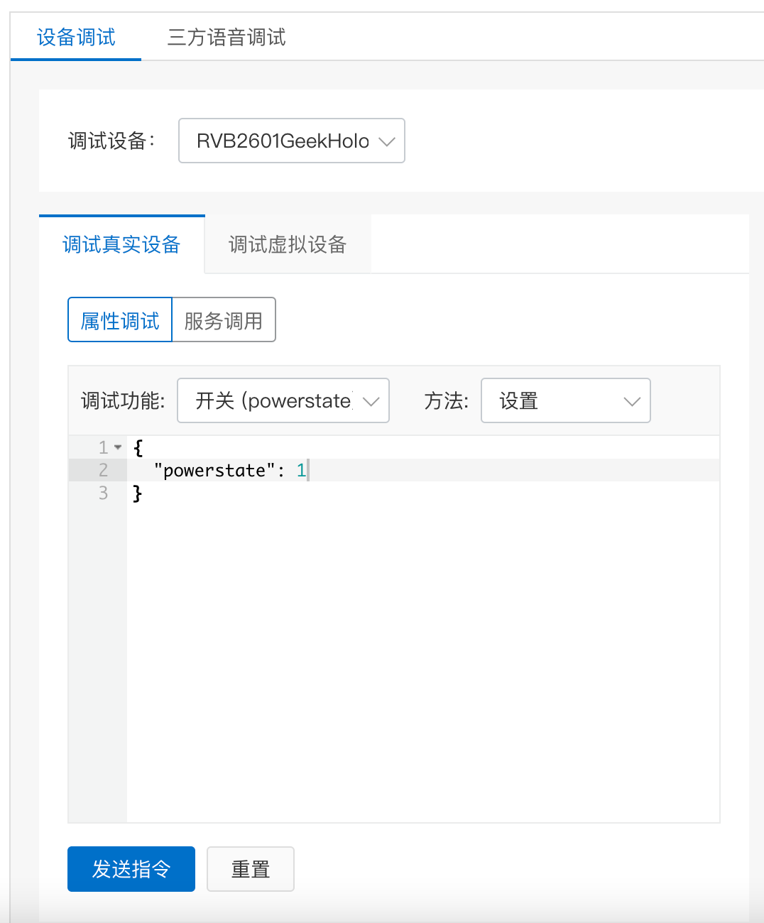
这时,我们就可以对智能灯进行在线调试了。打开阿里云生活物联网平台的设备调试页面后,我们点击测试设备条目中的“调试”操作,就会进入在线调试页面。
|
||
|
||
在调试页面中,我们可以选择调试功能“开关”,方法选择“设置”。下面的消息框中会自动根据物模型准备好JSON格式的消息体。
|
||
|
||
|
||
|
||
点击“发送指令”后,这个属性设置消息就会发送到智能灯,实现对智能灯的控制。当然,你也可以选择其他的属性进行设备测试。
|
||
|
||
另外,我们还可以在公版云智能App中测试、使用已接入平台的智能灯。这里要怎么实现公版云智能App的控制呢?你需要进入“批量投产”页面,然后点击“配网+App下载二维码”,根据提示下载云智能App到手机。接着,点击“产品发布”完成产品上线。
|
||
|
||
|
||
|
||
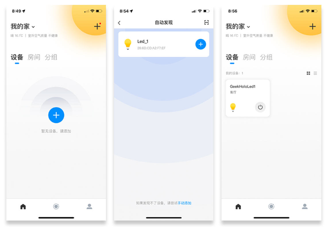
完成这些准备工作后,你就可以在云智能App中添加我们的测试设备了。这里需要注意的是,要保证App和智能灯设备都连接到同一个Wi-Fi网络中,否则,云智能App是不能发现智能灯设备的。
|
||
|
||
App上的具体展示内容如下:
|
||
|
||
|
||
|
||
## 小结
|
||
|
||
到这里,我们就完成了智能灯的联网控制开发任务。
|
||
|
||
在实验中,我们使用的物联网平台是阿里云生活物联网平台,整体的创建流程与第17讲的平台类似。重点是物模型的定义和人机交互界面的设计。
|
||
|
||
在智能灯的联网控制开发中,我们使用W800模组提供的AT指令来实现平台的交互。AT指令是通信领域常用的控制协议,在嵌入式领域也有广泛的应用,你可以基于本实验对它进行扩展学习。在连接Wi-Fi网络时,我们会使用到YoC嵌入式系统平台提供的网络管理器模块。关于YoC是什么,和模块的关系又是什么,我会在下一节详细讲解。
|
||
|
||
## 思考题
|
||
|
||
最后,我给你留一个思考题。你可能注意到源代码中有些函数的前面有static关键字,有些函数前面没有这个关键字。比如函数parse\_living\_msg前面有static,这是为什么呢?欢迎你在评论区写一下自己的理解,也欢迎你将这一节分享给你的朋友,大家一起交流学习。
|
||
|